What does the service cover?
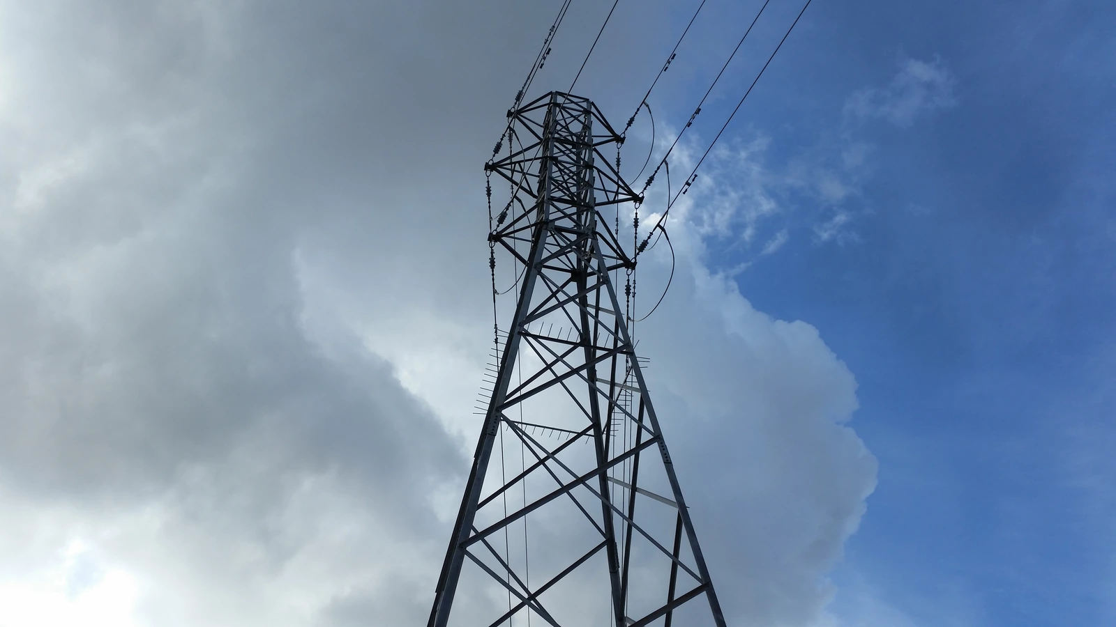
Overhead transmission lines
Coordinating towers, conductors, insulators and routes on the plan and profile.
Underground transmission lines
Cable routes, ducts, special crossings, joints, cross-bonding and earthing details.
Drawings, calculations and deliverables
Plan and profile
Plan and profile from the supply point to the connection point at horizontal 1/2000 and vertical 1/500 scales, marking angle points and terminal towers.
Route plan
A 1/25000 topographic route plan including terminal tower and angle-point coordinates.
Site plan
Connection points and cable routes on existing mapping or a topographic base at 1/1000, 1/2000 or 1/5000.
Cable laying drawings
Cable laying plans at 1/1000 or 1/2000 on planning, cadastral or surveyed bases, showing duct type, cable characteristics, lengths and entry/exit nodes.
Cable ducts and special crossings
Scaled duct and special crossing details based on cable characteristics, circuit count and laying arrangement.
Material installation and section details
Scaled installation drawings and cross-sections for materials used in underground transmission lines.
Cable sectionalising, cross-bonding and earthing
Installation drawings for cable joints, sectionalising and cross-bonding points, and the earthing system.
Tower leg section calculations
Tower leg sections and calculation records derived from field measurements where required.
Tower schedule
Tower types, chainages and spans, design ranges, angles, crossings, conductor arrangements, insulator types/quantities and leg details.
Technical support from data to implementation
Review design inputs
Review available design, connection, field or cadastral information against the scope.
Prepare the technical package
Coordinate the drawings, calculations and schedules for the service.
Institutional submission and technical follow-up
Submit the package to the relevant institution and follow its technical review.